Sign up for daily news updates from CleanTechnica on email. Or follow us on Google News!
Greetings, serious geothermal supporters. This letter to the editor addresses articles touting the baseload, climate impact, and large-scale PPA capabilities of hot dry rock geothermal (HDR) systems, in particular Enhanced Geothermal Systems (EGS). The letter also answers increasing recognition by government, investors, offtakers, and clean energy proponents for the needs to drill fewer wells, very significantly reduce costs, and gain more reservoir control in order to produce much, much more energy from our geothermal resources, while mitigating water and seismicity issues.
As you know, EGS and other method developers, have in recent years received no shortage of notoriety and government and investor funds. What none of the practitioners have received, though, are accolades respecting some amazing amount of energy output. This is because there is no amazing output, except for the amazingly low kind, the unfinanceable kind. Still, much is promised by and riding on geothermal’s potential.
HDR production methods take two main forms familiar to supporters: AGS and EGS. AGS, “advanced geothermal systems,” are closed loops (a well and a production tubing) and generate 0.4MWt (gross) per mile of 325°F bore. Notably, an AGS well can lose ½ of its bottomhole temperature during its first day of operation. Multi-well EGS does essentially the same, but can substantially deplete more around its first month after generally 0.6MW to 1.5MW output, depending on the operational mode. Reasons for such performances are many, but mainly involve low heat access, low effective heat transfer surface area, and all but nonexistent heat replenishment.
With respect to low heat, most HDR developers, oddly, tout use of unrelated horizontal drilling practices, as borrowed from oil and gas, having developed such capabilities because that is how their resources are best accessed. Heat, however, is found at vertical depth, and the same total length horizontal drilling ignores 50% of geothermic availability below it. How does the use of horizontal drilling make sense here?

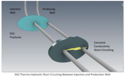
Then, minimizing effective heat transfer area, multi-well EGS logic follows by constructing a series of minimal, effectively single-point perpendicular wellbore-fracture hydraulic connections (above) through which water is injected for heating. This slightest of arrangement, unaligned with its purpose, mostly guarantees hydraulic and thermal “short-circuiting,” where the injected flow takes the path of least resistance to the production well egress, but not across the intended fracture’ heat transfer surface areas. (Please see Figure A.)
Attempting to make up for the resulting low heat recovery (<10%), HDR developers tightly pack induced fractures by the hundreds at as little as 30’ (also an O&G number) spacing. Because 1000’+ separation is required for timely HDR reservoir heat replenishment, the congested EGS fracture model is far remiss in this regard. Further, recent inflation among oil and gas service companies has driven some fracturing operations upwards of $500,000 per day. Where frequently only two reservoirs may be created daily, EGS stimulation designs requiring potentially hundreds of the operations present an additional CAPEX burden of several millions. Not ideal.
Clearly, the fundamentals are not on the right side for obvious type HDR method design, and that any solutions must lie in effecting all opposite positions.
The DGS Technical Solution

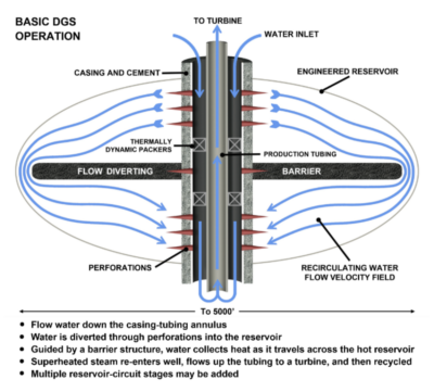
The DTS Technologies Geothermal System (DGS) is a reconfiguration and streamlining of EGS’s original (opposite condition) vertical approach commenced more than 50 years ago. Comprised of O&G and geothermal practices in place for decades, DGS resolves HDR’s fundamental shortcomings — all of them, especially the production part. Inspection of the sketch at right (Figure B) first shows the elimination of two-well horizontal expense in favor of a single well construction that performs both the fluid inlet (formerly injection) and the production task through the well annulus and then the production tubing, respectively. This dual functionality occurs only after vertical drilling most economically accesses maximum depth and heat, both of which are ultimately more than double that exploited by current HDR.
Increasing effective heating surface area requires another opposite condition. Because induced fracture- reservoirs propagate in a generally vertical direction, it only makes sense that their host wellbore is drilled as co-planar with a fracture’s inclination. This is so that a full hydraulic connection can be created between the well-annulus and the reservoirs. The well annulus-reservoir connection is made by perforations cut through the well casing along the entire height of each reservoir. Please see Figure B and Figure C for the resulting flow inlet and outlet details. With direct and full length fluid connectivity in place, detailed control over reservoir hydraulics may then be conducted, thereby causing complete working-fluid-to-HDR-surface area contact and thermal energy “sweep” recovery of nearly 100%. Such a level is in stark contrast to the generally 6% recovery traditional to EGS.

Then, because of the earlier noted traditional premature heat depletion issues, DGS reservoir design calls for 1100’ separation between reservoirs by undisturbed rock to enable continuous utility scale heat replenishment. More precisely, 1500’ separation is a preferred distance, one not cannibalistic to replenishment, but 1100’ separation has been found more optimal, balancing practical deep well construction requirements and overall heat production. Due to its extractive efficiency and system massiveness, only 15 “induced DGS circuits” are required to produce in excess of 110 MWt initial baseload or firm output and then 50 MWt average 24/7 output for 20 years. DGS power production is upwards of 30X over other geothermal methods, depending on metric. 30X more energy and 1/6 the cost.
Also in stark contrast with recent EGS proposals adding a second 100 fractures, the refined DGS concept with its greatly reduced fracture count represents a further cost savings of millions, per well.
The DGS Resolution of HDR’s Other Challenges
Connected natural fracture systems in the subsurface occur anywhere and are the source of two serious problems for geothermal: water loss and seismicity. During reservoir stimulation or during production related re-injection, the hydraulic pressure generated infiltrates natural fractures, even those microscopic in size. Continued pressure causes flow upwards of thousands of feet away from the geothermal operation, resulting in millions of gallons of water losses and potential communication and lubrication of geologic faults leading to earthquakes. There are means of mitigation, however.
Depth. Increased vertical depth not only increases heat, but it also adds weight against natural fracture voids, shrinking or closing them altogether. Higher fracture closure pressure from added depth causes natural fracture systems to disconnect, thereby limiting or eliminating their ability to carry fluids away.
The DGS Economic Solution
Just as geothermal’s technical solutions require reaching certain thresholds in order to produce substantive power from HDR, namely depth, heat, surface area, and alignment among subsystem functions, so too does its economics. By contrast, due to low output, irredeemable design, and high end operational expense, multi-well EGS and other developers propose miraculous cost reductions of 90% to avoid remaining among the costliest of energy sources at some $20M/MW CAPEX. Even at one-half of the true expense vs. output, the multi-well concept is neither profitable nor financeable. However, and not surprisingly, by again taking opposite positions, DGS-HDR can instead become the lowest cost of any power source. These points summarize how:
- DGS single well, vertical drilling — in simple terms, the same drilled length accesses 2X higher bottom hole temperature in comparison with the two well horizontal EGS approach. MW-intermittent (MWi) drilling CAPEX for DGS vs. EGS = $1.27M/MWi vs. $8.8M/MWi at 1300 GPM vs. 800 GPM respective flow rates. Noteworthy, proposals to increase multi-well EGS well diameter, flow capacity, and horizontal lengths to double current 1.5MWi to 1.7MWi output, would increase well cost by 3X to nearly 4X.
- Steam flash vs. ORC binary conversion — DGS sweep efficiency and thermal maintenance enables use of 3X higher yield flash conversion and to <400°F bottom-hole operating conditions. Comparative flash vs. binary CAPEX may be ⅓ or less. Flash maintenance generally involves biennial inspections and one week’s downtime. Long running ORC O&M and related ranges $.01 kWh to $.03 kWh, per DOE.
- Operations and parasitic loads — DGS is self-circulating to approximately 420°F operating temperature, as a vacuum is formed due to the differences in annular inlet and bottomhole tubing temperatures and fluid densities. Relatedly, DGS does not require substantial cooling. Other geothermal suffers 30%—40% parasitic loss, owing primarily to reinjection work. Cooling can traditionally consume another 50%.
The sum of DGS’s creating all favorable power output and economic positions is a $24 kWh cost structure, constituting the lowest LCOE and most economic power source of all types — clean or not. The low cost translates to 70% or better net margin clean baseload power sales.
The DGS Solutions History
The DTS team have practiced and/or developed high temperature subsurface geothermal operations for others worldwide since 1980, including massive scale and high temperature hydraulic fracturing in excess of 500°F, well construction exceeding 600°F, thermally resilient multiset packers, and water conformance settings exceeding 400°F. Among the more notable projects are:
- Cooper Basin, Australia
- Attaka, Borneo
- Kamojang and Kalimantan Indonesia
- Nigorikawa and Hachimantai, Japan
- Bicol Belt and Negro Sulu, Philippines
- Imperial Valley, USA
By Jeffery A. Spray
DTS Technologies, LLC
Have a tip for CleanTechnica? Want to advertise? Want to suggest a guest for our CleanTech Talk podcast? Contact us here.
Latest CleanTechnica.TV Videos
CleanTechnica uses affiliate links. See our policy here.
CleanTechnica’s Comment Policy


