Efforts to increase capacity can often result in reduced capacity, according to Martin Engineering.
When greater production is needed to meet rising demand or lower quality raw materials require more tonnes to be processed, many operators simply speed up the conveyor.
But rather than increasing capacity, this often results in reduced capacity, because changes in the trajectory of the discharged material can cause build-up and clogging in hoppers or chutes.
In some cases, the proper answer to the question, “Can we increase capacity to the existing conveyor?” should be, “No, we need to start over”.
Conveyor design
Conveyor design is an iterative process. When purchasing a conveyor at the lowest capital cost, the design is likely to use the maximum loading capacity on the narrowest belt travelling at the maximum speed for the raw material, while meeting only the minimum safety standards and codes.
If the goal was to design a conveyor with the lowest cost of ownership over its intended life, it was likely designed with less than maximum loading, a slightly wider belt and the capacity to run at a reasonable speed, while exceeding minimum safety standards and code requirements. The best practice is to re-establish the original design intent and compare it to the existing conveyor.
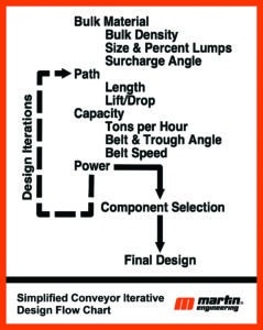
Image: Martin Engineering
Conveyor technology changes over time, particularly in belting and calculation methods.
The most recent Conveyor Equipment Manufacturers Association (CEMA) design guide, ‘Belt conveyors for bulk solids’, requires predicting power requirements within -0 to +10 per cent of actual.
It’s vital to define the problem the conveyor upgrade plan is trying to solve.
Not understanding the primary reason for an upgrade could cause address symptoms rather than root causes. A new design might not address the primary need for a performance upgrade. For example, if the chutes are plugging or there is spillage, it might not be a conveyor issue but instead an operator or maintenance issue.
Component standardisation
It is usually desirable to try to use belting, idlers and other components that are available elsewhere at a site or are common supplier stock items. This may not always be possible, but the capital cost alone should not force a less than optimum design solution.
Because increased tonnage might escalate idler loads, rolling components may require a higher load capacity to obtain an acceptable life. It is important to consider the lifecycle costs of design and component selections.
A process called ‘loading on the transition’ – loading the conveyor before the belt is fully troughed – is a common way to save money on installation, but it is also one of the biggest contributors to damage and the release of fugitive materials.
Loading on the transition best practices:
- If space permits, rectify the loading so it starts at the second fully troughed idler
- Vertical curves, if properly designed, are not an issue but the design calculations need to be verified if the belting or tonnage changes
- Using bend pulleys for convex curves rather than a spaced array of troughing idlers is often a source of spillage and should be avoided
- Diverter plows and other devices, which tend to force the belt to one side or the other, should be located where the belt has enough distance for returning to running centered in the idlers
- When loading round particles or operating in wet environments, a belt incline of 5° or less will help create a mass that prevents rolling or fluid cargo from flowing backward toward the tail pulley; the best practice is to load horizontally and transition into the slope
- For round material, consider installing curtains along the slope to knock down bouncing particles and allow them to form into a stable profile
Belt width and trough angle
The trough angle is initially selected based on experience or the existing idlers for standardisation.
Belt width is selected by calculating the cross-sectional area of the bulk material by assuming a troughing angle, an idler with three equal roll lengths and the surcharge angle, lump size and flowability of the bulk solid being handled.
There are two important cross-sectional areas to consider: CEMA 100 per cent full and full edge-to-edge.
The 100 per cent full area is based on a standard belt edge required to prevent spillover between idlers as the belt sags on the carrying run. The full edge-to-edge loading is used to calculate the maximum potential load on the structure.
The best practice is to select the belt width based on 85 per cent of the CEMA 100 per cent cross-sectional area to allow for surge loads, off-centre loading or normal mistracking.
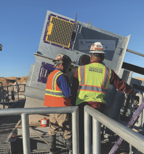
Image: Martin Engineering
Two common techniques can be incorporated into a new or complete conveyor design to make future upgrades less costly.
The first is changing the trough angle of the idlers to raise the capacity by increasing the cross-sectional area. In new designs, consider using 20° idlers. Upgrading to 35° idlers is a 27 per cent increase in cross sectional area, and going from 20° to a 45° trough angle is a 37 per cent increase.
Although 35° idlers are fairly standard, it is important to note that for retrofit upgrades going from 35° to 45° idlers is only an eight per cent cross-sectional area increase.
The second common technique for new construction is to design the structure for the next wider belt and use CEMA wide-base idlers.
The mounting dimensions of the wide-base idlers allow for a future replacement with a wider belt. For example, if the structure for the 1200mm belt and 20° surcharge angle using 35° trough idlers was designed for wide base idlers, the belt width could be increased to 1400mm, resulting in a 33 per cent capacity increase with the same trough angle and belt speed.
Changing from a 35° to 45° trough angle and the wider belt and idlers would result in a 90 per cent increase in cross-sectional area. This method is not often used because there is resistance to increasing capital cost for a wider and higher load-bearing structure, higher material mass and larger drive. But it’s an excellent approach if there’s a goal of increasing capacity in the future.
CEMA provides some guidance on belt speeds for different material classes in ‘Belt conveyors for bulk materials’. Generally, a wider belt operating at a lower speed will reduce fugitive material release, given the potential for fugitive material release is directly proportional to belt speed and capacity.
The lower CEMA-recommended belt speeds should be used in the first iteration of the design. Additional iterations can then be tried by changing the belt width, trough angle and belt speed to arrive at a reasonable solution.
Discharge chute
The discharge chute will need close review for a capacity increase. The trajectory path should be plotted so the stream of material affecting the chute does not create a situation where there is zero or negative vertical velocity on impact with the chute.
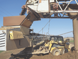
Image: Martin Engineering
If the material can stay suspended at the impact location, it will increase the chance of build-up and blockage of the chute. If the angle or liner is changed, it must not create a slow flow situation where material backs up and accumulates in the chute.
The discharge chute cross sectional area should be a minimum of four times the cross-sectional area of the loose bulk solid.
The design of the loading chute and skirtboards requires close attention to minimise release of fugitive material.
CEMA uses two-thirds of the belt width for the inside dimension of the loading chute skirtboards, regardless of belt width. Idler fouling and spillage can happen when uneven loading causes the belt to drift to a degree that there is an opening between the inside of the chute wall and the edge of the belt.
Best practice in design considers the amount of allowable mistracking plus the thickness of the sealing system to determine the distance from the edge of the belt to the outside of the skirtboards as the minimum dimension on each side.
This feature appeared in the May 2024 issue of Australian Mining.

 - CleanTechnica")

